
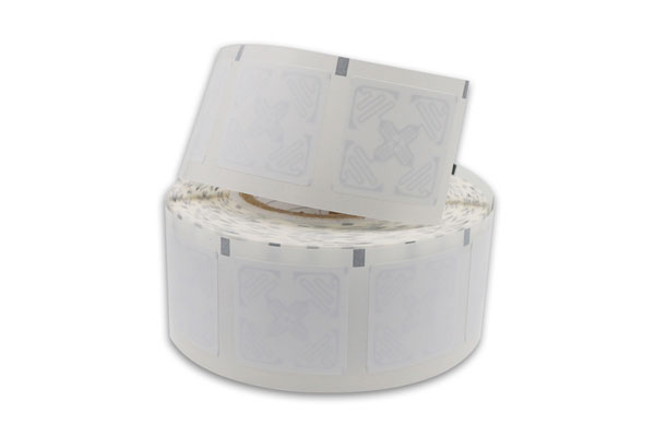
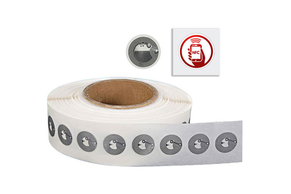
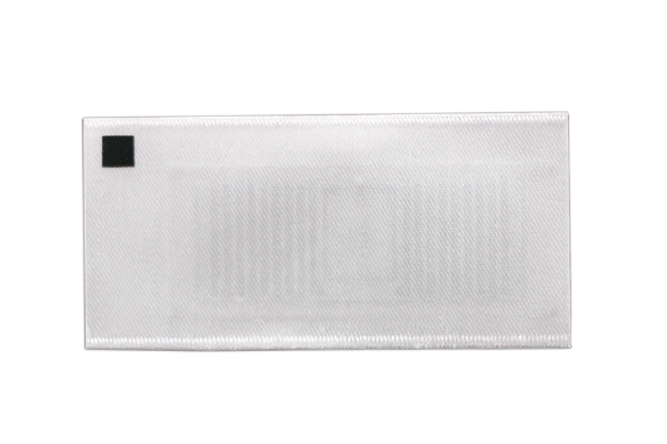










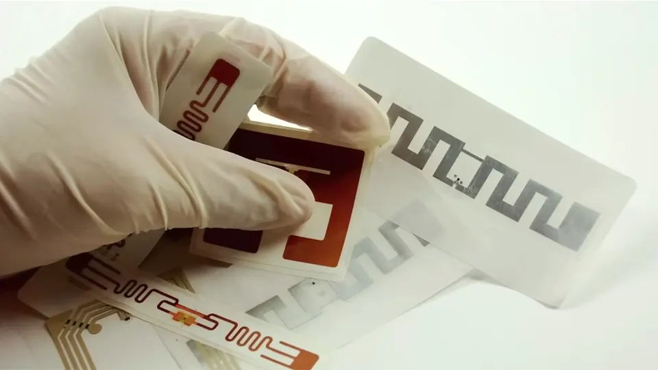
A buyer can specify the same RFID chip for two tags and still receive products with noticeably different read performance. This happens more often than expected in UHF RFID projects. Two inlays may both use NXP UCODE 9, for example, yet one can maintain reliable reads at several meters while the other performs poorly when attached to the same product.
The difference is rarely explained by the chip alone.
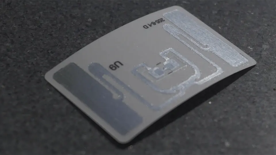
An RFID IC is part of a much larger RF structure. The antenna, matching design, substrate, tag dimensions, IC position and the material carrying the tag all affect how efficiently the chip receives energy and communicates with the reader. Even the same finished tag can behave differently after being attached to metal, plastic, glass or a liquid-filled container.
For system integrators and RFID buyers, this distinction matters when comparing samples or quotations. The chip model is useful information, but it is only one specification of the finished RFID tag.
A UHF chip does not define the finished tag
Modern UHF RFID chips are highly capable devices. NXP UCODE 9, for instance, operates across the 860–960 MHz UHF RFID range and has a published read sensitivity of -24 dBm and write sensitivity of -22 dBm. It also provides 96-bit EPC memory, 96-bit TID memory, 100,000 write-cycle endurance and 20-year data retention.
These are important IC specifications, but they describe the chip rather than the complete inlay.
The chip has to receive enough RF energy from the reader to power its circuitry. It then modulates the reflected signal through the antenna so that the reader can identify the tag. If the antenna does not collect and transfer energy efficiently, the sensitivity of the IC cannot be fully translated into field performance.
An Impinj M730 or M750 can be used in the same way. The IC may remain unchanged while the antenna geometry, substrate and tag construction are redesigned for a different application. A compact apparel label, a warehouse label and an anti-metal tag may therefore use the same IC while having very different RF characteristics.
Several parts of the finished construction influence this relationship:
- antenna geometry and physical dimensions
- impedance matching and resonance
- substrate and surrounding materials
- IC position and tag orientation
This is one reason chip comparisons alone can produce misleading conclusions. A lower-cost tag is not necessarily using an inferior chip, and a tag using a well-known IC is not automatically the better-performing product.
The antenna decides how much of the chip’s potential can be used
The antenna is where many of the practical differences start to appear.
A passive UHF tag has no battery supplying power to the IC. The reader provides the RF energy, and the antenna has to capture that energy and transfer it efficiently to the chip. This requires the electrical characteristics of the antenna and IC to be properly matched.
The relationship is usually discussed in terms of impedance. An RFID IC presents a complex input impedance, while the antenna has its own impedance. The matching network or antenna structure is designed so that energy can move efficiently between the two.
A small mismatch can reduce the amount of usable power reaching the chip. In a marginal application, that difference may show up as a shorter read range, missed reads or inconsistent performance at certain frequencies.
Antenna dimensions also matter because UHF RFID antennas are tuned structures rather than simple pieces of conductive material. Changing the length, width, shape or spacing can shift the resonant behavior of the tag. The result may be a different operating bandwidth or a different response across the 860–960 MHz range.
This becomes particularly important when a tag is designed for a specific market. European UHF RFID deployments commonly operate around 865–868 MHz, while North American systems use a different section of the UHF spectrum, generally around 902–928 MHz. A tag optimized for one region cannot simply be assumed to provide identical performance in another.
The antenna therefore has to be designed around the chip, the required frequency range and the intended application. Changing the IC without reconsidering the antenna is rarely a simple substitution.
Put the same tag on different materials and the result can change
A tag that performs well in the lab may behave differently once it is attached to a real product.
Cardboard cartons are usually relatively straightforward for conventional UHF labels. Plastic containers can introduce more variables, depending on the material and wall thickness. Water and other liquids interact strongly with UHF electromagnetic fields, while metal can alter the electromagnetic environment around the antenna and shift its tuning.
This is why a standard UHF label used on a cardboard box cannot automatically be transferred to a metal equipment housing.
For a metal application, the antenna is often separated from the conductive surface with an appropriate structure or material. The tag is then tuned around that construction rather than around free-space conditions. Flexible anti-metal tags, ABS anti-metal tags and PCB anti-metal tags are examples of designs created for different mechanical and RF requirements.
Liquid applications require the same kind of application-specific thinking. A label attached directly to a bottle containing water, for example, sees a very different RF environment from a label placed on an empty cardboard carton.
When testing an RFID tag, the actual target surface should therefore be treated as part of the specification. A useful sample test normally includes:
- the real tagged material
- the intended attachment position
- the actual reader and antenna
- the expected tag orientation
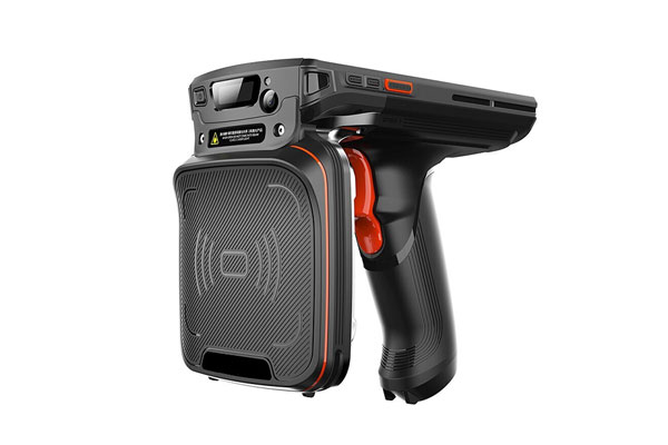
Reader configuration can also change the result. Transmit power, reader antenna gain, polarization and installation height all influence the energy available to the tag and the signal returned to the reader. A laboratory read-range number should therefore be treated as a test result under defined conditions, not as a universal property of the chip.
Smaller tags require more careful antenna engineering
Tag size is another reason identical chips can end up in very different products.
A larger physical area gives the antenna designer more room to work with, but size alone does not determine performance. Antenna geometry, resonance and matching still have to be optimized within that space.
NXP’s UCODE 9 documentation provides a useful example. Its published design information shows that a smaller antenna can be developed from a 50 × 30 mm design toward approximately 42 × 20 mm, with the specific example indicating potential savings of up to 44% in aluminium and plastic usage.
That does not mean a 42 × 20 mm tag will automatically perform as well as every 50 × 30 mm tag. Once the antenna becomes smaller, its electrical behavior changes and the design has to be retuned.
IC placement is another detail that becomes more important in compact tags. The location of the IC relative to the antenna and matching structure affects the electrical characteristics of the complete inlay. A few millimeters can matter when the available antenna area is already limited.
The substrate also plays a role. Paper, PET, foam, ABS and other materials can create different electrical conditions around the antenna. Encapsulation, protective layers and spacers can change the distance between the conductive antenna and the tagged object as well.
This is particularly relevant when the same chip is used across several product families. The IC may be identical, but the physical construction around it can be completely different.
What should be compared when two tags use the same IC?
When two suppliers quote the same chip, the comparison should move beyond the IC specification.
1. Confirm the exact chip.
“UHF RFID chip” is too broad for a meaningful comparison. Specify the actual IC, such as NXP UCODE 9 or Impinj M730, together with the required memory and protocol characteristics.
2. Compare the complete inlay design.
Look at tag dimensions, antenna structure, substrate and IC placement. Two products carrying the same chip may use completely different antenna designs.
3. Test the tags on the target product.
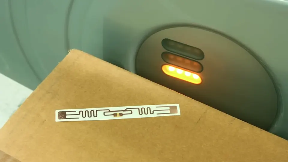
Samples should be attached to the actual carton, garment, plastic container, metal asset or other target surface. Free-space testing alone does not show how the tag will behave in the field.
4. Check the required frequency region.
A European deployment around 865–868 MHz and a North American deployment around 902–928 MHz place different demands on antenna tuning and bandwidth.
5. Use the intended reader configuration.
Testing should account for the actual reader, antenna, mounting position, transmit power and tag orientation whenever these details are known.
This approach gives the procurement team something much more useful than a chip comparison. It shows whether the complete tag is suitable for the application.
The specification should describe the application, not just the chip
An RFID quotation that says “NXP UCODE 9, 96-bit EPC” leaves out many details that determine field performance. The IC may be correctly specified while the actual tag remains poorly defined.
Before volume production, the following points are worth fixing in the technical specification:
- target material and product type
- tag dimensions and construction
- operating frequency and region
- required read distance
- reader and encoding equipment
- environmental conditions
- attachment method
- memory and encoding requirements
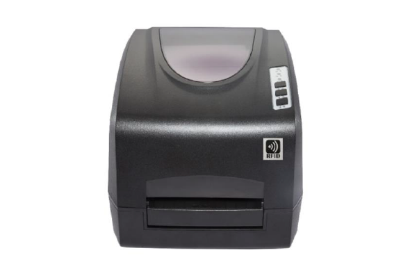
For printed RFID labels, encoding and printing equipment should also be considered during qualification. A tag may communicate correctly with a reader but still create problems during continuous printing and encoding if its construction is unsuitable for the selected RFID printer.
For example, DTB-P10U is an RFID printer model that can be considered when a project requires RFID label printing and encoding. The relevant point is not the printer model itself, but whether the selected inlay can be consistently printed, encoded and verified within the intended production workflow.
This becomes increasingly important at higher volumes. A small inconsistency in antenna tuning may be barely noticeable during a ten-piece sample test but become a significant operational issue when thousands of labels pass through a printer or hundreds of tagged items are read during an inventory cycle.
The same RFID chip can therefore sit at the center of two very different tags. NXP UCODE 9 remains UCODE 9, and Impinj M730 remains Impinj M730, but the antenna surrounding the IC, the materials underneath it and the way the finished tag is constructed can change the behavior of the complete product.
For RFID buyers and system integrators, the more useful question during qualification is not simply which chip is inside the tag. It is how that complete tag performs on the intended product, at the required frequency, with the actual reader setup. That is where the differences between seemingly identical RFID tags become measurable.
