










As warehouses move from manual handling to conveyors, automated storage and retrieval systems (AS/RS), autonomous mobile robots (AMRs), and high-speed sortation, RFID performance increasingly depends on where the RF field is created and how goods move through it.
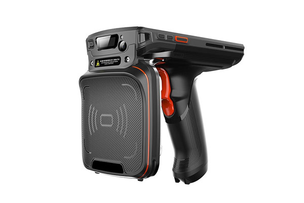
A reader may have enough output power and a tag may offer strong sensitivity, yet the system can still produce missed reads, duplicate reads, or stray reads when the antenna layout does not match the actual movement of goods.
The basic questions are simple: Where does the RFID event need to happen? How long will the tag remain in the read zone? From which direction will it approach the antenna?
Consider a conveyor running at 2 m/s. A 0.6 m read zone gives an item only about 0.3 seconds inside the zone. At 0.5 m/s, the same zone provides about 1.2 seconds. That fourfold difference can affect antenna placement, reader timing, polarization, tag selection, and overall read reliability.
Define the RFID Read Point Before Positioning the Antennas
A reliable automated warehouse RFID installation starts by defining the read points, rather than deciding where the antennas should go first.
Common read points include receiving docks, shipping doors, conveyor transfer points, packing stations, sortation lanes, storage interfaces, and handoffs between conveyors and material-handling equipment.
Each location has a different purpose.
At a shipping portal, the system may need to confirm that a specific pallet has crossed a physical boundary. On a conveyor, the requirement is usually to identify cartons, totes, or trays while they are moving. At a storage interface, the system may only need to confirm that an item has entered or left a controlled area.
That distinction is important because maximum RF coverage does not necessarily produce better RFID data.
A field that extends too far can detect tags on nearby pallets, staging lanes, adjacent conveyors, or products waiting for another process. The EPC read itself may be valid, but the resulting event can still be associated with the wrong warehouse activity.
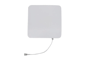
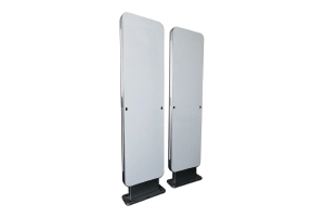
For a dock door, the read zone should follow the pallet path as closely as practical. Dual-sided antenna placement can help when pallet tags may face either side of the portal. For conveyors, antenna positions should be based on the actual location and orientation of RFID labels on cartons, totes, trays, or other unit loads.
Two rules are particularly useful during site planning:
- Define the required read boundary before adjusting reader power or antenna gain.
- Test the layout with loaded pallets, cartons, and normal warehouse traffic rather than an empty installation area.
The goal is controlled identification, not the largest possible RF footprint.
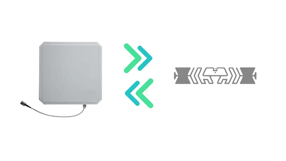
Conveyor Speed Directly Affects RFID Read Time
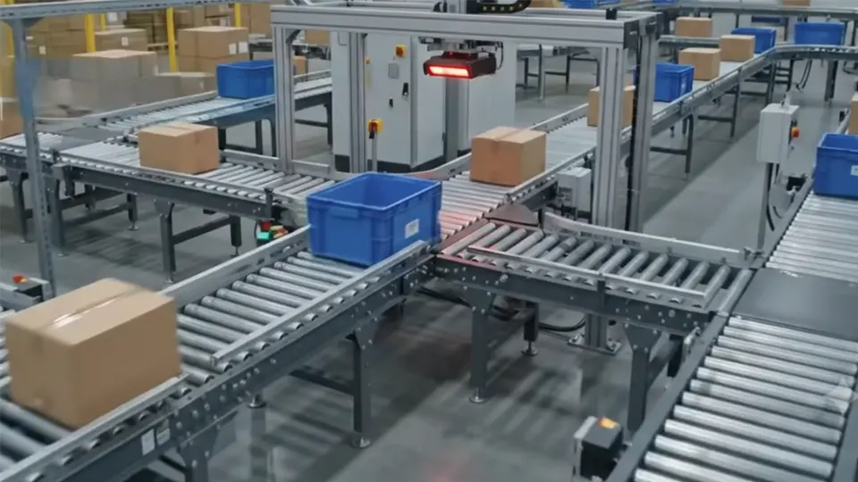
Conveyor applications require particular attention because the available RFID reading window can be very short.
The basic calculation is:
Dwell time = read-zone length ÷ conveyor speed
For example, a 0.6 m read zone provides about 1.2 seconds of physical dwell time at 0.5 m/s. At 1 m/s, that falls to 0.6 seconds. At 2 m/s, it drops to just 0.3 seconds.
These figures describe how long an item physically remains inside the zone. They do not represent guaranteed RF communication time.
A reader may need to switch between multiple antennas during that period. If four antennas share the reading cycle, the effective exposure available to each antenna can be considerably shorter than the total time the item spends inside the physical read zone.
This is where antenna placement, tag orientation, polarization, and reader timing begin to interact.
A conveyor tunnel can provide better control of the RF environment. Top and side antennas can target tags on different carton faces, while a lower antenna may help when labels can appear underneath a product or tote. The appropriate arrangement depends on conveyor construction, product dimensions, tag location, and the direction of travel.
Metal rollers, frames, guards, chutes, and nearby machinery can also affect the RF field through reflection and absorption. As a result, an antenna layout that looks evenly balanced on a drawing may behave differently once the conveyor is running with real products.
Antenna count should therefore not be determined simply by conveyor width. The more important question is whether the antenna arrangement provides sufficient RF exposure at the actual tag positions while keeping unwanted reads outside the process.
Read Range Is Not the Same as Read Efficiency
Longer read distance is often treated as an automatic performance advantage. In automated logistics, excessive range can create another problem: the RFID system may identify the correct tag but associate it with the wrong location or process event.
Consider a shipping door next to a pallet staging lane. If the antenna field extends beyond the doorway, tags on pallets waiting in the staging area may also respond.
The warehouse management system (WMS) then receives a valid EPC, but the event may be interpreted as a shipment movement even though the pallet has not crossed the shipping boundary.
For this reason, a controlled read zone is often more useful than maximum read distance.
Reader output power, antenna gain, antenna angle, polarization, physical shielding, trigger sensors, reader timing, and software filtering can all contribute to controlling the effective read boundary.
The same principle applies to conveyor systems. A tunnel should cover the intended product path without unnecessarily exciting tags outside that path.
This becomes especially important when multiple conveyors run close to one another. Without adequate RF control, a tag moving on one conveyor may be detected by an antenna serving another lane.
A practical design sequence is:
- Mark the physical boundary where the RFID event should occur.
- Measure conveyor speed, tag position, product spacing, and expected tag orientation.
- Test successful reads, missed reads, duplicate reads, and stray reads under normal operating conditions.
- Adjust antenna position, polarization, reader power, and timing before adding more antennas.
Adding antennas should be an engineering decision based on the measured RF environment, rather than the default response to missed reads.
RFID Tag Selection Can Change the Antenna Layout
RFID antenna design cannot be separated from the tag itself.
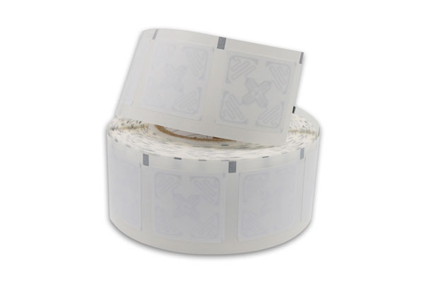
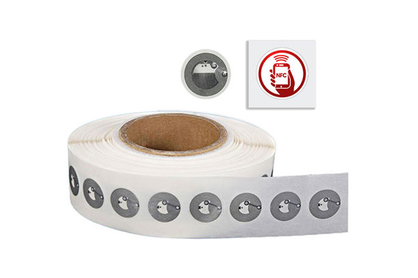
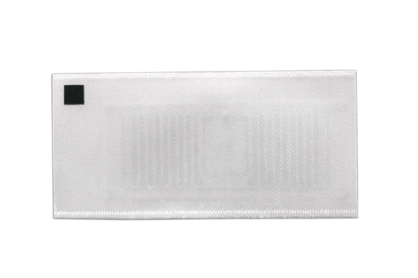
The RFID IC, inlay antenna, substrate, mounting surface, and operating environment all influence how much RF energy is available for communication. A label attached to corrugated cardboard can behave very differently from one mounted on a metal tote. Liquid-filled products introduce additional RF loss, while closely packed tags can interact with one another on a dense pallet.
IC sensitivity is one factor in this equation.
NXP specifies a read sensitivity of -24 dBm for UCODE 9, with 96-bit EPC memory. UCODE X is specified at -26.2 dBm. Impinj specifies -24 dBm for M730 and -25.5 dBm for M830 under the conditions stated in its product documentation.
These figures help illustrate the RF margin available from different ICs, but they should not be treated as a direct prediction of warehouse read distance.
Finished tag performance depends on much more than the IC. Inlay antenna geometry, substrate material, mounting surface, operating frequency, reader configuration, polarization, and the surrounding RF environment all have an effect.
That becomes particularly important when the RFID tag has to fit into a limited physical area.
A higher-sensitivity IC can provide additional design margin, but the finished inlay still has to perform on the intended product. UCODE 9, for example, supports 96-bit EPC memory and is specified at -24 dBm read sensitivity, while UCODE X is designed around higher sensitivity and smaller tag applications.
For warehouse applications, tag selection should therefore be validated against the actual mounting condition rather than based on the IC specification alone.
A UHF label using UCODE 9 or Impinj M730 may perform well on corrugated cartons, while a metal tote, liquid container, or dense plastic bin may require a different inlay structure. The reader and antenna may remain unchanged, but the tag construction can still need to change.

Validate the RFID Antenna Layout on the Warehouse Floor
Even a technically sound antenna layout requires physical validation.
RF behavior around racks, conveyors, forklifts, metal structures, loaded pallets, and moving equipment is difficult to reproduce accurately through drawings or simulation alone. A small change in tag orientation can alter coupling, while a nearby metal component can create a localized weak area or unexpected reflection.
Testing should cover both normal and difficult operating conditions. Different tag orientations, minimum and maximum product spacing, full and partially loaded pallets, maximum conveyor speed, different carton sizes, and nearby RFID activity should all be considered.
The most useful measurements are operational rather than theoretical. Track successful reads, missed reads, duplicate reads, stray reads, and the time required to identify each item.
For example, a conveyor processing 60 cartons per minute moves one carton every second. If the spacing between cartons falls to 0.5 seconds, the RFID system has to distinguish consecutive items within a much tighter event window.
A system that performs well with isolated cartons may behave differently when products arrive continuously at production speed.
Three tests should be repeated after every significant antenna-layout change:
- Run representative products through the complete read zone at production speed.
- Repeat the test with difficult tag orientations and the actual warehouse load.
- Compare read performance at the target-zone boundary and immediately outside it.
The objective is not simply to achieve a high RFID read rate. The more important goal is to maintain a reliable relationship between physical movement and RFID events.
When antenna placement, tag construction, reader settings, and warehouse process timing are properly aligned, RFID can provide consistent item and pallet identification with fewer false events and less dependence on manual intervention. In an automated warehouse, that controlled relationship is what turns RFID reads into dependable operational data.
